orthotropic bridge deck FEA simulation (improved)
Abbreviations and explanations
- OBD = Orthotropic Bridge Deck
- HGV = Heavy-Goods-Vehicle
Introduction
This is taking
my 6th June 2016 initial orthotropic bridge deck simulation
, then
- all geomtric features remain identical
- the boundary movement constraints are changed to better represent
an OBD
- the load is changed to 50000N (5tonnes-force) spread over a
0.1m-square area (approximately representing a HGV's
tyre-contact-patch)
- the mesh is refined and the the elements are changed from
corner-nodes (only) to (with) midside-nodes ie "quad4" to
"quad8"
Obvious imminent improvements to apply
A single HGV would have more tyres (tires) landing on this OBD
section, at the axle-spacing - which the model would benefit from
being included in the load-condition.
Would the "external" constraint conditions for an OBD-section be
better represented by applying no-movement/no-rotations to the ends of
alternate T-bars?
(Are the plane-of-symmetry conditions in this model reasonably
realistic?)
Number of elements and nodes
- Elements : 19392
- Nodes : 57757
The model
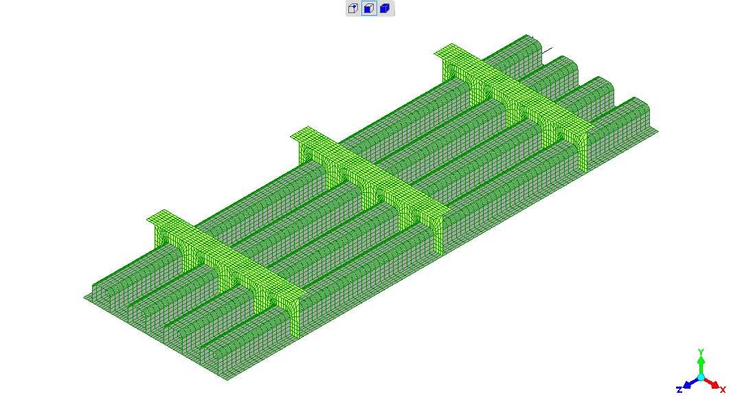
Geometry and meshing
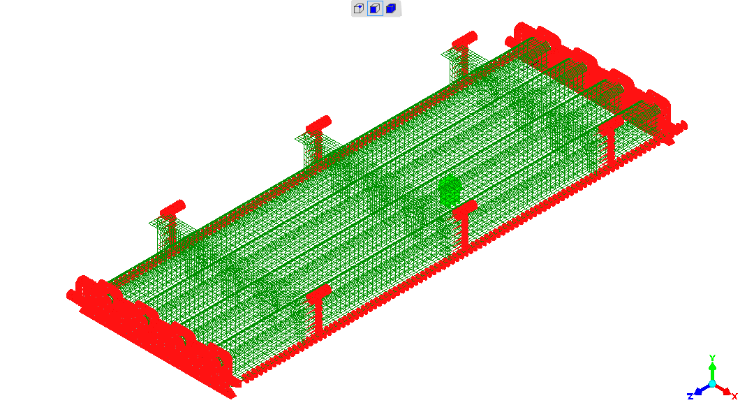
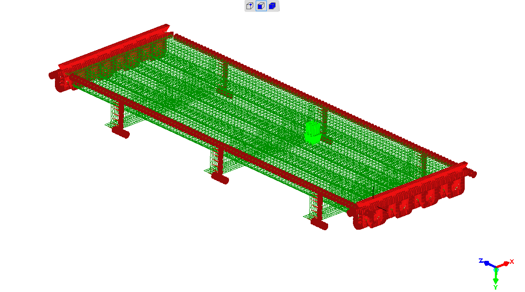
Upside-down view, showing ribs and T-bars
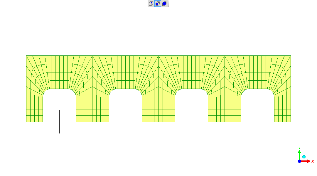
End-view, upside-down, showing meshing of T-bar web
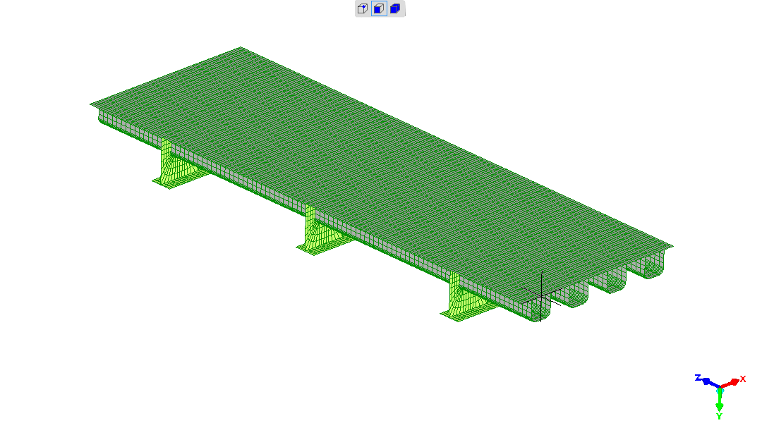
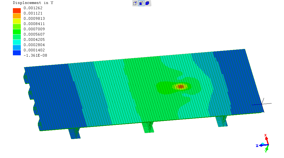
Deck surface, as would be seen in a "fly-by" of the bridge
Local view showing mesh details and constraints
Details of geometry and matching of mesh where ribs and T-bars join is
one aspect shown here
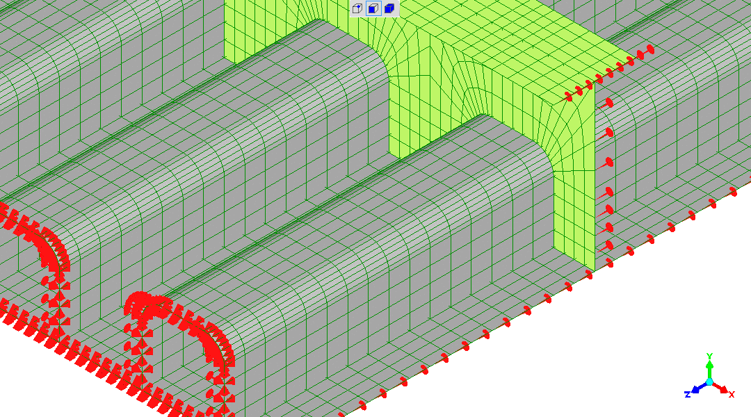
Movement constraints and load-application of the model
These images are very cluttered.
The constraints (shown in red) and loads (shown in green) are:
- the "z-ends" cannot move in the x-, y- and z-directions (load
passes to some unseen support here), nor can they twist in the
x-direction (it's a plane-of-symmetry, with this OBD section connected
to its mirror-image identical in geometry, restraint and load)
- the "x-edges" cannot twist in the z-direction (is another
plane-of-symmetry)
- The applied load lands over a small area at the mid-width, midway
between two of the "T-bars"
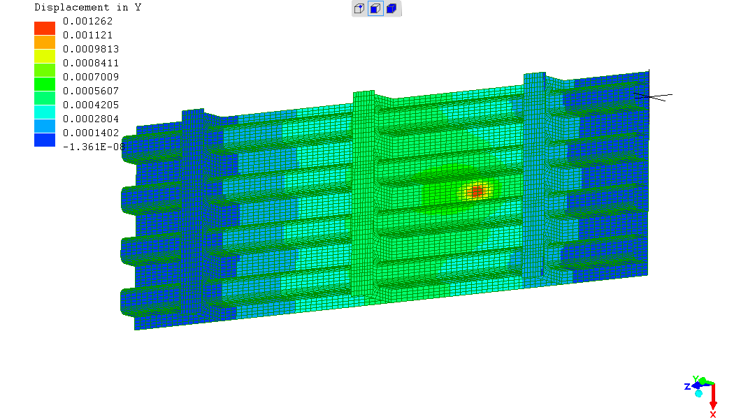
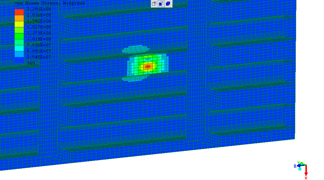
The computed structural behaviour
Deflection under applied load in the vertical ("y") direction
Deviatoric (tendency-to-deformation) stresses caused by the loading
(R. Smith, 02Oct2016, 04Oct2016)