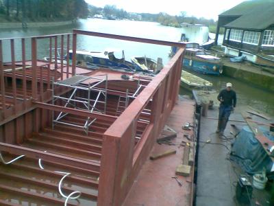
General view of superstructure building on floating hulls at the wharves
This page is here with the intention of enabling anyone to see the nature of the work I do at a boatyard I now work at (at time of writing - mid-January 2008). The boatyard is on the River Thames, above locks separating it from the tidal Thames, on the Western side of London.
I came to the job based on my trade skills as a "welder-fabricator" from working in the land-based construction industry.
Broadly, the work areas of the yard are as follows
Here is a picture which gives an overview of the work environment for building superstructures.
General view of superstructure building on floating hulls at the wharves
The first work I set to as foreman.
Temporary picture(?!)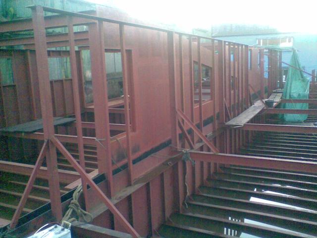
projbt_portside_myframe_10.jpg
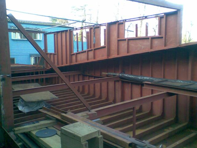
To interpret the image - there is the "sister" barge moored alongside to the left-hand-side of the image. My first work as foreman, seizing control of this largely stalled project, was to put up the superstructure structural and stiffener ribs rising off the "stringer" just below the top edge of the hull-side-plates, plus the top-plate delineating the top deck will start.
Here is how I set about it with my team:
Firstly:
The Major vertical ribs were set upright to both the "stringer" plate
("fore-and-aft") and the transverse structural beams they sit upon
("port-to-starboard"). This was done using the
3:4:5 rule.
(Note : you cannot use a spirit-level on a floating hull!!! The hull
tips around constantly with motion of the water and what is in/on the
hull!!!)
The "squareness" was locked in place with offcuts of angle-iron
tack-welded "on the diagonal". These can be seen in the above
picture.
Secondly:
The intermediate stiffening ribs were tack-welded at the
accurately correct position on the stringer, and approximately upright
using a square off the stringer. However this tacking was done to
carefully leave the "third tack" accessible with a slitting disk in an
angle-grinder, near the top of the hull-plate. This was therefore in
an intermediate state of completion.
Thirdly:
The top-plate was put on top of the major verticals and stiffener
ribs, aligned and tacked to the major verticals.
Finally:
For each stiffener rib in turn, the "third tack" on the
was severed with a slitting disk and the rib was moved at the top to
its correct distance from one "end" of the major vertical and
top-plate, then was tacked at the top and re-tacked at the bottom.
Because window aperture frames have to be fitted between the verticals and the seams between the hull plates are made to align with the ribs, it is very helpful when that stage is reached for the initial framing to be accurately square.
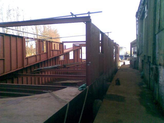
The team then moved on to the other side of the boat where there is a sloping walkway.
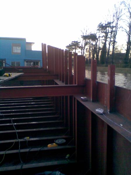
projbt_starboard_walkw_uprights_09.jpg
Even the apparently simple task of putting in the uprights between the "stringer" and the walkway required careful work. The length of most major verticals were annotated on cross-sectional drawings printed from the main drawing provided by the naval architect. However, one of the major verticals is not seen in any provided cross-sectional drawing - and only one stiffer rib is seen in any cross-sectional drawing. I therefore had to use the familiar equation for a straight line graph, "y-mx+c", to calculate the lengths of the stiffener ribs (I wrote a little program to do it, but ended-up using a spreadsheet).
As these uprights are quite short, there is no great opportunity or value in using the "3 4 5 rule", so the team used squares. However, all was not that easy for the major uprights (surprise, surprise!).
Sitting on the transverse beams, the location does not provide any good datum surface upon which to place a square for setting the fore-aft alignment. Considering the problem, the following picture shows my quickly improvised, fully satisfactory solution.
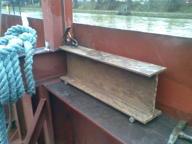
level_whatsit_11.jpg
The ribs are made parallel to the major verticals by making the top and bottom distances the same, inheriting their vertical accuracy from the major vertical members.
Why the painstaking work keeping dimensional accuracy and squareness? Well... You hope to save time later...
These pictures are of the "sister-vessel", which was started first.
sisbt_inhull_07.jpg
sisbt_superstr_05.jpg
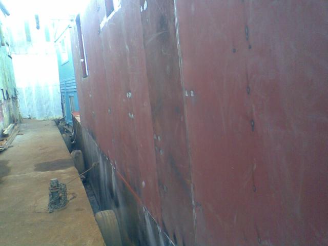
Here is a photo of a section of superstructure with the plates tacked in place but needing welding. That isn't hugely obvious in the photo. What you can see from different colours is the patchwork of different plates which need to to welded together into one whole.
sisbt_hullplate_tofullpenw_06.jpg
I demonstrated massive productivity increases in welding the superstructure plates together along all seams - something like at least 10 times faster (what I could do in about 20 minutes takes hours by established procedures).
A detailed description of the productive welding practice is given separately, should the details be of interest.
The quick snapshot is:
Welds were done like this with, using familiar Rutile electrodes
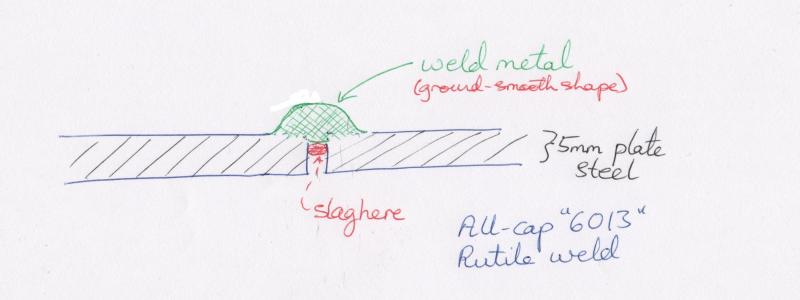
whereas I used deeply penetrative "cellulosic" electrodes for fast
welds needing little finishing
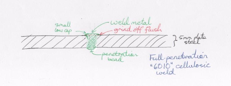
The influence of the rapid full-penetration practice is to be seen in what I have shown already. The rapid reliable fully penetrated root-run weld is only achievable when there is a gap between the adjacent superstructure plates which is fairly uniform in the range 1mm to 3mm. This is a tighter requirement that is currently generally achieved. Hence the accuracy with which my team has put in place the superstructure ribs. With other attention to detail like removing local high-spots from the hull plate top edges and blending the supposedly straight edge, the effort is to create a "cascade" of practices which leads to a tighter fit-up. Early indications running through the stages of assembling the superstructure framework are promising.
(R. Smith, 19 January 2008)