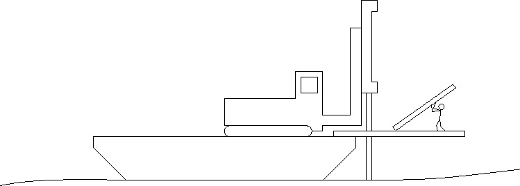
Schematic representation of the drilling at site - barge with drilling-rig, and the access platform (right-hand-side) to handle drill string. Barge deliberately grounded on ebbed tide.
Forewarning - the calculations are infeasible to carefully explain.
This is way more complicated than for, say, a Rectangular Hollow Section.
This would be interesting if you use Euler-Bernoulli beam theory and
calculations, and you follow the progression of my logic and
calculations.
I've tried to explain the jumps of logic as the calculation
progresses.
All dimensions in mm, unless specified otherwise.
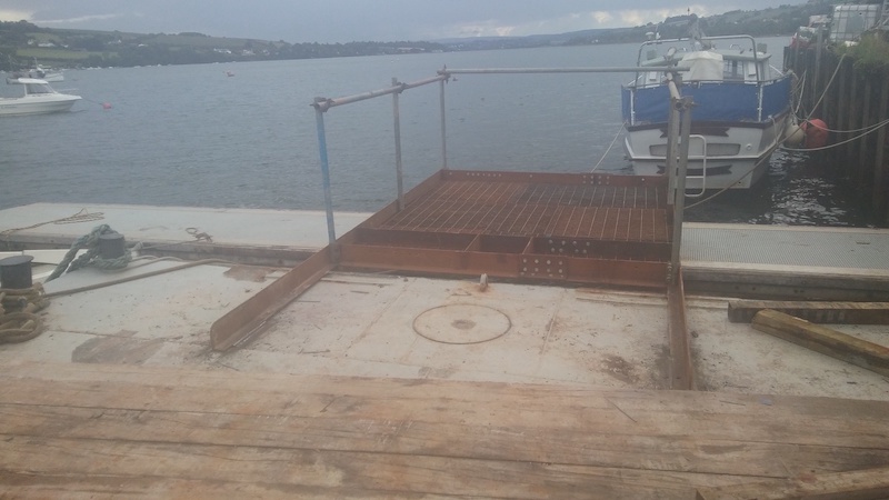
The platform cantilevering off the end of the barge enables the crew to work on the drill-string and install more length of drill string as the drilling progresses.
The crew on the platform are facing the front of the drilling rig.
Which is a land-based machine on tracks, driven onto the barge.
You cannot drill off a floating barge. Reason why a much more expensive jack-up is needed for drilling, in general.
The drilling is to install navigation markers in the inter-tidal range - the "drying zone". So the barge is towed to position at high water and is left riding on anchors. Until it grounds on the receding tide. Whereupon drilling can commence. Economical !! :-)
The main point of these calculations is showing that if you keep going
on a tenuous basis, the outcome can never-the-less be solidly very
good.
Which you can verify empirically at the end easily with a test load in
safe conditions eg the platform is only 150mm off the ground
when tested.
The assurance that the outcome is good is very high indeed despite the
tenuous journey the calculations took
The corollary is - there is no overarching logic to explain, in this
case.
Above and beyond that Euler-Bernoulli beam theory was used as a tool
as and when it could help.
Unequal angle can be thought of as "L"-section.
This is unequal angle - it's asymmetric - so so is the Second Moment of Area. There is no way the "Blue Book" will list Moment capacity because
Same calculation done in two slightly different ways
;; find neutral axis

;; n=sum(M)/sum(A)
;; take base of section - in "L" presentation

;; stay in mm for now
(/f (+ (* 65 10 5) (* 150 10 75)) (+ (* 65 10) (* 150 10)))
;; 53.83720930232558 ;; mm (! - not metres!)

(let ((a1 (* 65 10))(y1 5)(a2 (* 150 10))(y2 75))
  (/f (+ (* a1 y1)(* a2 y2))(+ a1 a2)))
;; 53.83720930232558
So the neutral axis is 53.8mm above the base where the outer surface of the short 75mm side is taken as the reference plane.
Function "ma2nd-rect-b-h-cx" calculates the "b.h^3/12" value for I,
the Second Moment of Area.
Function "ma2nd-a-y-parallelaxis" is applying the parallel axis
theorem for where that "b.h^3/12" part is on the cross-section.
 (+
  (ma2nd-rect-b-h-cx 10e-3 150e-3) ;; 2.8124999999999993e-06
  (ma2nd-a-y-parallelaxis (* 10e-3 150e-3)(- 75e-3 53.83720930232558e-3)) ;; 6.717955651703624e-07
  (ma2nd-rect-b-h-cx 65e-3 10e-3) ;; 5.416666666666668e-09
  (ma2nd-a-y-parallelaxis (* 65e-3 10e-3)(- 5e-3 53.83720930232558e-3)) ;; 1.5502974580854517e-06
  ) ;; 5.04000968992248e-06 ;; m^4

;; "Blue Book" => 501cm^4 => 501e-8 = 5.01e-06m^4
;; so agrees.
The steel is "S275", with nominal / minimum yield stress of 275MPa.
The previously calculated position of the Neutral Plane is being used.
;; sigma_max=My/I
;; M_max=sigma_yield I / y

(/f (* 275e6 5.04000968992248e-06)(- 150e-3 53.83720930232558e-3))
;; 14413.086960902861
;; = 14.4kNm
At start : distances measured which lead to the "1.67m" value for the location of the middle of the platform's deck area.
The cantilever beam formula is then applied.
;; point load at middle of deck = 2.44/2+0.450
(+ (/ 2.44 2) 0.45)
;; 1.67

(*
 (/f 14413.086960902861 1.67 9.81)
 2 ;; there are two beams
 )
;; 1759.5496421106243 ;; kg-f

;; if at end of deck
(*
 (/f 14413.086960902861 (+ 2.44 0.45) 9.81)
 2 ;; there are two beams
 )
;; 1016.7639800431634
;; 1 Tonne for even at tip (front) of deck
They seem reasonable, and experience / intuition suggests there's enough cross-bracing to stabilise the "L" sections against rotation for the lengths and loads-at-locations.
One would be needing more cross-bracing approaching the barge which provides the cantilever's fixing, towards which the stresses are increasing. It is the case that there is more cross-bracing there, where it gives the "moon pool" for the drill string.
The loadings which would cause the primary steel "L"-sections to bend, 1~3/4Tonnes-force in the middle of the deck and 1Tonne-force at the end of the deck looks right.
Those loadings at "plastic" failure are a bit lower than one might like. A bigger safety factor would be preferred. However, if the primary steelwork got much stronger, you'd have to consider the strength of the deck of the barge to take the leverage.
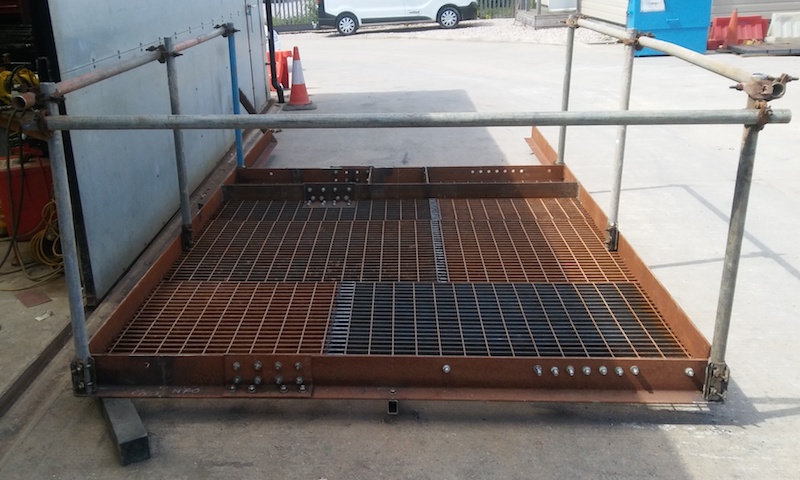
Not previously explained - the "L"-sections enable the deck gratings to be lifted to tip off mud / clay / silt of the drilling and be slotted back into place. That would be much less easily provided with anything but an "L" section. Which naturally provides a secure seat for the deck-grating.
Something else not previously explained - those bolted splice joints
enable the platform to be broken-down small enough to fit on
3~1/2Tonne flatbed trucks - "Transits" and "Mercs" typically.
Another economy and a logistical simplicity seeing as the available
trucks can transport the platform whenever.
The railings don't need to be considered here.
The deck grating has some strength, but is much more elastic than the
beam put in to support it.
So loads will pass to the secondary-steel support beam.
Jumping-ahead, yes a secondary deck support beam is attached to the
structure.
It can be seen on the underside of the deck end-on / fore-and-aft in
the first picture.
Its size has a "Goldilocks quantity" - just right - neither too big
nor too small. Logic as follows...
Were that beam to bend in overload, the deck grating would begin to
take more load.
The drilling operators would "get a tap from the clue-stick"
that they are doing something they shouldn't be doing, without being
put at risk.
That "clue-stick" needs to deliver its "tap" before the primary structural steelwork is overloaded - because that could be dangerous.
The logic applied, as a construction site worker...
There would be a large temptation to stack a lot of drill-string
sections on the platform, to speed-up the drilling operation.
If that were to happen at sea, while the barge is in transit to the drilling location, that could have several people, heavy drill-string sections and likely various tools tipping in a tangle into the sea. With potentially fatal consequences.
The potential consequences are not much less when the barge is grounded on the "drying zone".
In reality the drilling crew are more likely to experience an "Oh my
golly-gosh" (or words to that effect) moment as the platform does an
angle of bending then stops as the plastic hinge stiffens.
But given the potential consequences - that is unproven and anyway
nothing like enough safety margin.
Instructions of what to do and not do are far from the preferred reliance where consequences would be serious. Someone who didn't get the briefing. Crew tired from long days of work. Supervisor who had insomnia the previous night and is flailing around aggressively, giving orders without good thought. etc, etc.
On the other hand, these are experienced crew working in construction, so at all times they will be sensitive to indications of the current situation.
So - the deck must support the legitimate work, but must sag and take a permanent bend on an overload which is less than the load-bearing capacity of the primary steelwork - the cantilevering "L"-sections.
Yup, just fine :-)
Can do that no problem. Seriously...
It actually gets a bit better than that...
Is there anything available which is suitable?
Avoid having to put in an order for material, get it delivered, etc.
A piece of Rectangular Hollow Section of dimensions 60x40x3 was found.
This could be a possible candidate.
Its steel is "S355" - which can be taken as 355MPa yield strength.
Calculate the Second Moment of Area of the RHS60x40x3
(-
 (ma2nd-rect-b-h-cx 40e-3 60e-3)
 (ma2nd-rect-b-h-cx (* (- 40 3 3) 1e-3)(* (- 60 3 3) 1e-3))
 ) ;; 2.7385199999999993e-07 ;; m^4

;; agrees with "blue book"
The load-bearing capacity for the 2.44m length of the end-supported
beam
using the "Blue Book" tabulated Moment capacity - particularly given
that my value for "I" (Second Moment of Area) and the "Blue Book"'s
"I" agree.
Where the "9.81", as previous, is Earth's Gravity of 9.81N/kg.
;; M=WL/4 -> W=4M/L
(/ (* 4 3240.581999999999) 2.44 9.81) ;; 541.5320599588908

;; My first-principles calc for pure rectangular shapes gives this - 542kg - for 60x40x3 S355
That is perfect! 542kg central load at bending.
In real life, the load will be more distributed, dispersing across the
deck-grating with some load going directly from the grating into the
primary "L"-sections.
That said - considering the overall situation - that 542kg-force value
is reasonably indicative.
An experienced welder came by and, in line with general experience,
considered that the decking needed more support, indicating about a
quadrupling of the deck support steelwork.
With halving some of the spans, that would more than 4 times increase
the strength, and vastly increase the stiffness. The decking would
seem very stiff and solid.
A rapid firm intervention was needed to explain that the decking
should not be stiffened or strengthened.
The concept that secondary structure is designed to have a strength
less than the primary structure is familiar, and the timely
explanation was sufficient to keep everything on-track.
The experienced welder would have been exactly right if the primary steelwork had something like ten times the strength or greater.
The primary steelwork would start bending at about 1~3/4Tonnes-force in the middle of the decking area. That being accurately predictable.
For a decking-support-beam bending force of 542kg if a point-loaded in the middle of the decking area, for realistic more distributed loadings of many objects, the deck should plastically sag significantly before the primary steels bend.
Seems all good.
I called over a number of workmates and hailed a couple of project managers who were passing, and got them to stand on the outer end of the decking. As it was stood in the Yard only about 150mm above the floor. 8 and 9 persons - about 800kg. Enough.
Also to jump up and down on the middle of the deck.
Ulterior motive - that means a number of those going on the drilling crew and a couple of the project managers have seen the strength and have an image of the loading limit.
Returning to the loading test - I mentioned things get even better than just the load-bearing limits.
The decking has a springiness which instinctively indicates what maximum loading it can bear.
I stated earlier that I would always trust the crew at all times to be sensitive to by-the-second (of time) indications of whether all is well. Come tiredness, come foul weather, come what may. They are experienced Tradespersons.
The springiness gives a calibration of what you can carry onto the deck. It keeps conditions within-bounds, with the decking still "as made".
Then the "long-stop".
Yes if the indication of bounds were ignored (which isn't going to happen) then the deck support beam would bend. The deck-grating initially solely resisting the deck load would become unusably softly springing (like a trampoline sheet). Which would force a halt to the work with no-one harmed.
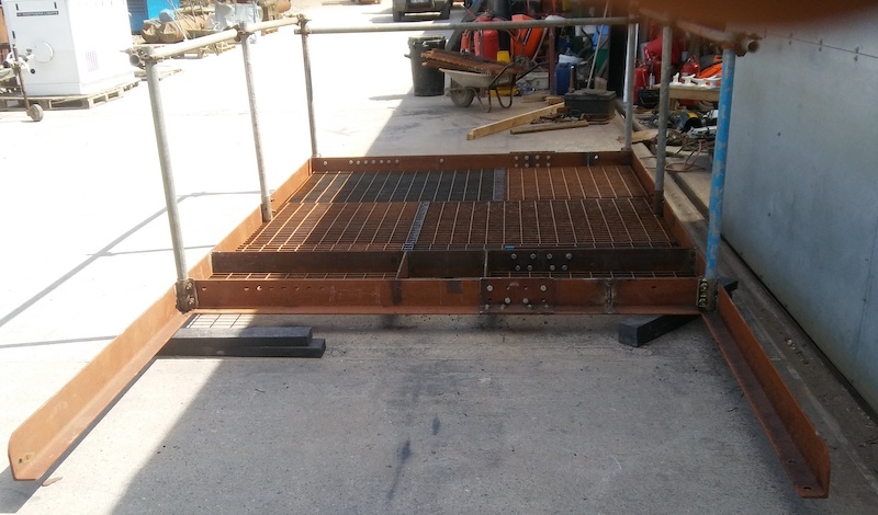
As seen in the pictures...
The structure felt so right, walking on it.
The decking is easy to move around on while carrying heavy weights.
Yet it has an elastic bounciness which gives the message of lightness
and limited strength
One point I made is that very tenuously-justified steps can lead to a very good outcome. This was indeed the case.
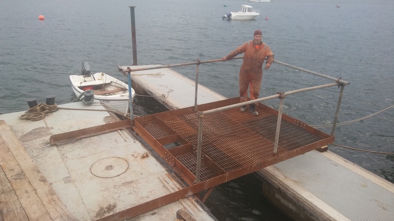
The platform returned to the yard only a couple of days after it was installed.
The success was that all the drilling work was done rapidly. Facilitated by the platform serving faultlessly.
The platform was considered so satisfactory and likely to have future uses, so was carefully cut from the barge and returned to the yard for storage.
That's right - doing the calculations was actually a rather enjoyable and brief bit of mathematical "sketching", while writing about it and trying to explain it was exhausting, took much longer and I was glad to see the back of it.
That's in spite of quoting my calculations of the time as-is, to keep the size of the task within bounds I would accept.
The mathematics - I found a project manager who had done structural
engineering at University, and ran them past him in a 2-minute journey
of displaying the maths, explanations and sketches.
It was such a "blast from the past" tapping into being an enthusiastic
engineering student 30 years ago that he was going around with a happy
smile on his face all day. This mathematics, engineering theory and
calculations stuff can become very spiritually satisfying when you get
to know it and like it.
As I said, to someone knowing the practical context, it took 2 minutes to share how I came by those answers - 1 Tonne-force, 1~3/4Tonnes-force and 542kg-f.
Very satisfactory result.
Benefit of doing calculations demonstrated.
(R. Smith, 14Mar2021, 15Mar2021 (maths vs writing, edits), 23Mar2021 (fig., edits), 25Mar2021 (edits inc. ma2nd-L))