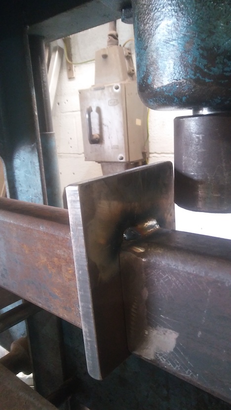
First try. Bearers here at 600mm separation - not the 320mm of the test.
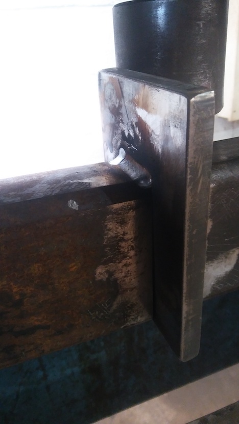
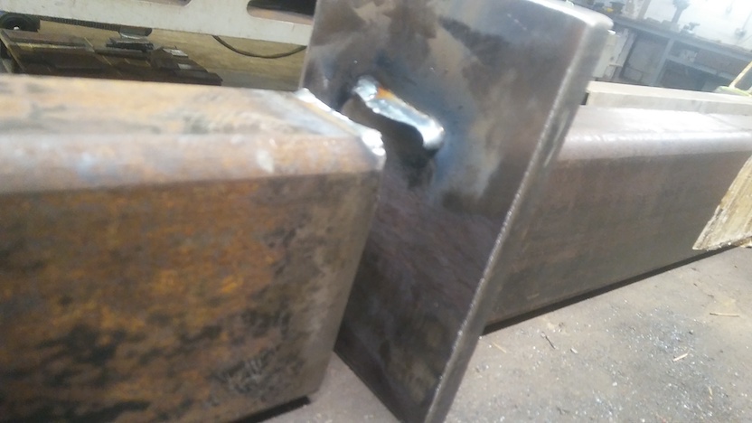
Test sample beam upside-down, showing one T-fillet weld
... and the T-fillet weld on the opposite side of the central plate
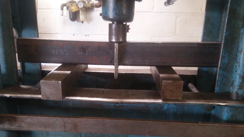
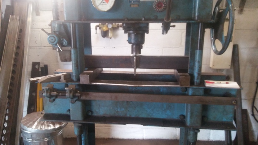
The test - press, bearers and beam weld sample set-up
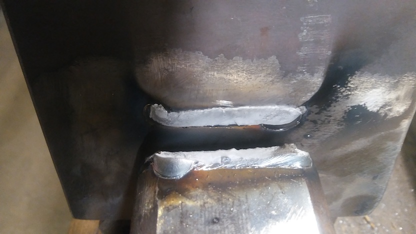
The fracture surface(s). Near beam presented upside-down; plate presented "correct way up" (in orientation as put in the press for testing). Fracture is almost planar and is a very fine dimpled apparently ductile "microvoid coalescence" fracture judged by characteristic matt-grey appearance. The fracture is seemingly at or near the weld-metal to parent-plate (the RHS) fusion boundary.
Separated halves of the sample presented "as they match", but upside-down to show the fractured weld
Breakage was abrupt with loud "bang" and elastic spring of parted sample halves.
Note even as the test showed itself as qualitatively interesting and possibly useful...
Overall - test method is a resounding (!!) success, even as it stands now.
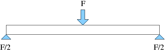
The test, probably best visualised as seen in the two photographs showing the overall test, is a static system. After pumping the press, the forces settle to a static equilibrium. This means the nett sum of forces must be zero. Without losing sight of the overall generality: the sum of (linear) forces is zero and the sum of moments ("twists", "torques") is zero.
This easily visualised mechanical system remains so right up to the breaking point. Whereupon the pieces of the test sample do "develop motion" / "cease to be static" (!).
This fundamental basic Newtonian insight of "sum to zero" is our way in to obtaining the force in the weld in relation to the force the press piston is exerting. This will almost certainly be a in a simple ratio - and that proves to be the case.
The "sum of forces = 0" is easy to see, but is "tautological" and doesn't enable us to deduce anything. You can see that, with a system symmetrical about the press piston centre, the two bearers each resist the press-piston force with half that force vertically upwards by each bearer upon the sample ends.
In the derivation I am about to present, I have already seen this and jumped straight to the system of Moments.
This is what the beam with fillet welds applies "in return", in satisfying Newton's Laws - "sum to zero" - particularly obviously for a static system.
The press is applying a force with its piston - the value shown on the "F=P.A estimate" force gauge. So the test piece must be identically resisting in applying that same force back upon the piston - Newton's equal-and-opposite ("equal but opposite") force...
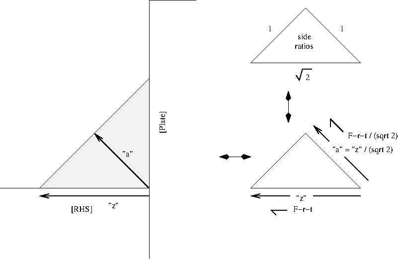
This is what the press is applying:
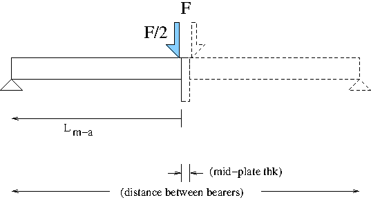
(PDF graphic)
which is the "M_s = F/2*L_m-a" applied Moment (see derivation
following). This "applied" Moment is "clockwise".
This is what the test-beam must be reacting where the weld attaches
the RHS to the central "mid" plate:
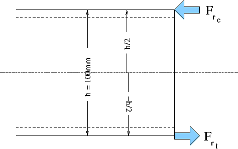
(PDF graphic)
which is the "M_r = F_r_t.h/2+F_r_c.-h/2" equal-but-opposite reacted
Moment (see derivation following). This "reacted" Moment is
"anti-clockwise".
That these two Moments, the applied and the reacted, must be equal but
opposite (clockwise and anticlockwise), in order to have a system
which is doing nothing when equilibriated ("settled down") to the load
applied by the pumped-up press, is the basis of the derivation
following.
This logical statement appears mathematically in the line "M_s = - M_r".
Symbols used in developing the derivation:
By Newton's Laws
M_s = - M_r
which is the fundamental underpinning of this analysis.
I derive for each "half system" - given two identical back-to-back systems about the press-piston central vertical axis...
applied Moment for "system"
M_s=F_p/2*L_m-a
v
system
press
moment-arm
for the reaction - symmetrical about section centre ("the neutral axis")
M_r=F_r_t.h/2+F_r_c.-h/2
F_r_t=-F_r_c
(previous two lines / statements - that must be so - instinct says
that - proof not visualised; symmetry about the RHS's
longitudinal-horizontal centre being the basis of the instinct about
the equilibrium)
M_r=F_r_t.h/2-F_r_c.h/2
M_r=F_r_t.h/2+F_r_t.h/2
M_r=F_r_t.h
combining the applied and the reaction (guided by Newton's Law(s))
F_p/2*L_m-a=-F_r_t.h
the "minus" will signify that the press is applying a downward force while the sample with weld is reacting with an upward force
-F_r_t.h=F_p/2*L_m-a
F_r_t.h=-F_p/2*L_m-a
F_r_t=-F_p*L_m-a/2h
"L_m-a/2h" is a dimensionless ratio
Restating and expanding the comments:
As the force across the weld F_w = F_r_t,
F_w=-F_p*L_m-a/2h
ignoring signifying direction of force, in mathematical notation
|F_w|=|F_p|*L_m-a/2h
So we have exactly what we hoped would "drop-out" if we worked the
derivation.
The simplicity means, on a practical level, that we can freely vary
the bearer position to make the weld breaking force higher or lower
at-will, so that breaking force is somewhere in the mid-range of the
press's ability. Not too high for the press to break the sample
(bearers too close together); not too low that you are trying to judge
a tiny force reading (bearers too far apart).
Bonus - as "L_m-a/2h" is a dimensionless ratio, we don't even have to
"watch" our distance units - we can measure in whatever familiar units
we want - in a workshop typically in millimetres - so long as we use
the same units for bearer-spacing and section-height :-)
This is all totally fantastic out-turn of events!
Now to input numbers / values.
I've done my maths "inline" with the text-editor's lisp ability,
injecting the answer into this buffer being worked upon.
That means if you want to read my maths, you will have to adjust to
the "lisp style" operator prefix notation (rather than the familiar
"on-paper" "infix" notation), between the brackets denoting each lisp
"sexp" ("s-expression"). Then there's one or two other quirks from
getting the lisp interpreter to give what is physically meant here.
";" is the symbol for "a comment" in lisp (what's to the right-h-s of
this the computer ignores) - which I've made syntactic use of with
";;"'s and also breaking up statements for the human reading.
There's some "infix notation" for the human developing the maths, and
some prefix notation for the lisp expression executed in-line here.
L_m-a/2h=...
Some measurements which are the input values to this arithmetic:
L_m-a=(320-12)/2 ;; (/ (- 320 12) 2e0) ;; 154.0
L_m-a/2h=154/2*100=154/200= ;; (/ 154 200e0) ;; 0.77
So there we have it,
"L_m-a/2h" = 0.77
for this test set-up with a 100mm tall RHS and 320mm between the
bearers.
F_w=
(*
(* 18 1000 9.81) ;; 176580.0 ;; force the press is exerting (N)
0.77 ;; the geometric ratio for this set-up
) ;; 135966.6 ;; N
or another way to put it
(* 18 0.77) ;; 13.86 ;; Tonnes-force
So we have already deduced that each test weld is reacting with 13.86 Tonnes-force tensile at the instant one of the welds broke.
Onwards - the weld - 6mm leg-length.
When I welded it, I made that so.
In standard weld terminology, the leg-length (fillet size measured
along the "plate" surface - the "face" / "edge" of the triangular
shape - is given the symbol "z". Such that we could denote the size
of the fillet weld as "z6".
More symbols
and more measurements (some restated)
sigma_f-z=F_w/(L_z.L_w)
(*
(/ 135966.6 (* 6e-3 40e-3)) ;; 566527500.0
1e-6) ;; 566.5274999999999 ;; MPa
That is a notable value - which deserves significant comment - which will come a bit later...
What if consider shear (Wikipedia) along the throat?
Noting F_w = F_r_t,
cos45=(F_w/2)/s
(/
135966.6 ;; N
(* 2 (cosd 45)) ;; 1.4142135623730951
) ;; 96142.90487487883 N
the (sqrt 2)/2 on F_w and on L_z cross-cancel - likely has equal shear stress on any plane between the longi-leg and the throat (??)
Little demonstration - "cos45" and "root-2/2" are equal,
given "=" is a question, a test, for equality in emacs (the text-editor's) lisp
(= (cosd 45) (/ (sqrt 2) 2)) ;; t
where the answer "t" means "true" (anything that is not "t" is "nil")
here it is...
(/
(* 135966.6 (cosd 45)) ;; 96142.90487487885
(* 6e-3 (cosd 45) 40e-3)) ;; 566527500.0
which,
disregarding sub-negligible "floating-point error" on the computed
values output by the emacs lisp interpreter,
is one and the same as the calculated stress along the fillet boundary
between weld metal and the "parent" steel of the RHS.
567MPa - that is a familiar break stress for a weld.
I can't be "leading" on this - see data-sheets for "G3Si1" / "ER70s-6" GMAW / MIG wire from the major welding consumable manufacturers - Esab, Lincoln Electric, etc - plus any others you may choose to look at.
Basically - 560MPa is the expected breaking strength (ultimate tensile strength) of "G3Si1" weld metal.
[07Feb2021 note - don't jump to conclusions yet - the "S355" steel constrained to not plastically deform might behave under load in ways not producing familiar numbers - with systematic reasons to suspect the "S355" steel in these circumstances might abruptly fracture at around the 560MPa of weld metal break]
My calculated value "is too good to be true".
That has the look of
On that note and at that juncture, I will leave the quantitative analysis as "to be continued..." - were there to be more data to evaluate.
The problem is - this can't be real. If it were that easy to obtain
the weld strength of a fillet weld, it would already be done that
way. You can know this from competitiveness to get the best results
cheapest, which gives very reliable deductions where there are many
participants acting independently.
Uniaxial tensile testing machines big enough to test meaningful fillet
weld samples have to be able to apply at least 100Tonnes-force - which
make them enormous beasts, well above the size of a commercial
test-house's "tensile testing machine".
Something I was genuinely completely unsure about - there seemed the
possibility that the weld strength in an apparent shear loading would
calculate as being about half the weld's tensile strength. It is a
familiar result via arcane arguments that the shear yield is half the
uniaxial tensile yield.
I need to consult on that.
Given all considerations...
I'm leaving things at that, feeling rather bemused.
(R. Smith, 24Nov2020, 28Nov2020 (added maths analysis), 05Dec2020 (added analytical derivation figs), 06Dec2020 (clock anti-clock), 07Feb2021 (F_r_t=F_w, aname))