This is about my aspiration to learn Ultrasonic Testing (UT) for examining welds
July 2012 and have got UT training started. Including loan of a UT set.
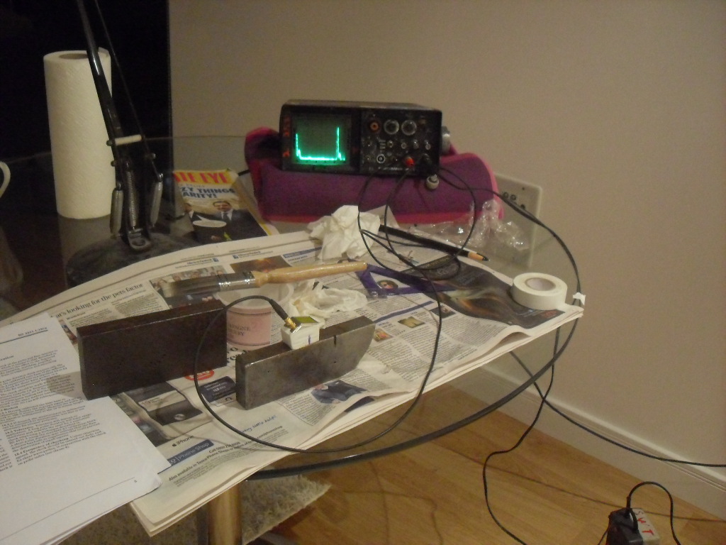
This is an "analogue" set with no computer assistance. Know the principles first! If you can use a set like this you can use a digital UT set wisely.
Initial stage is to be able to calibrate the set. After demonstration
in the training, I am working to BS4331-1:1978. Whatever it says do,
do it.
BS4331-1:1978 is a superceded and withdrawn British Standard.
However, like can be found in other cases, the "old" British Standards
can be very easy to work with / to for practical investigations.
I used a "Sonatest" block, which can be seen in the earlier picture. Indeed the "Sonatest" block is not part of any Standard (?), and I have already been finding that its small size means it is not that accurate; particularly for calibrating the angle of a shear-wave / angle probe. However, it is the portable block which has the great virtue of being the one I've got.
Here are the 9 calibrations of BS4331-1:
(here is as-written record of calibration - measurements and calculations)
These have to be done from regularly to every time you change the probe - in line with what the Standard says.
So here is the next step. I've done the BS4331-1 calibrations and my next challenge is to try to locate the position of drilled "target" holes in a test block using the UT method. Of course, because the "targets" are drilled holes, you can see the things! - and measure their position with a rule. So with a bit on honest work, you can get an estimate of your ability with UT to
These are with a shear-wave (angle) probe.
Sorry no sketch of this commonly used technique.
Does it have a name in the Trade?
This target hole 2mm diameter was drilled into the "thickness" face of a 19mm plate test-block.
In this first measurement, I had already calibrated that the "45 degree" probe is
sending out a beam at 45degrees.
Then I obtained these measurements:
Reasonable start - with a rule the target hole is measured at 10mm depth and 25mm from the datum.
Hopefully I have tightened-up calibrations by this stage...
Here is the target block.
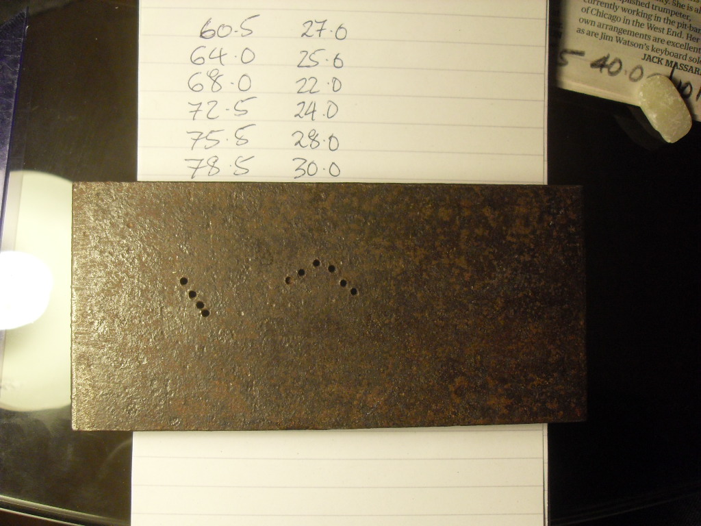
I am only working with the "upside-down tick" shaped array of holes.
The left-hand-side-most hole is only part-drilled. The written numbers on the paper-pad are the (x ("across"), y ("depth")) locations of the holes as measure with a rule from the LHS top corner.
However, for honesty and to avoid the natural tendency of the mind to seek "correct" or "better" values, I did the UT measurements first before ever applying a rule to these drilled holes.
The "45degree" probe used was calibrated as having an actual beam angle of 46.6degrees
Here are the UT measurements.
As recorded, it isn't naturally easy to make anything of them.
Apart from - there are too many "targets" identified...
The target at the apex of the "upside-down tick" should be seen twice
- once with the probe facing "forward" and again with the probe facing
in the "reverse" direction towards the datum.
But there are too many reflectors identified, even given that.
| px | tbd | dir | |
|---|---|---|---|
| (mm) | (mm) | (f/r) | |
| 30.5 | 40.0 | f | unsure of ... |
| 32.0 | 35.0 | f | unsure of ... |
| 37.0 | 36.0 | f | |
| 43.0 | 32.0 | f | |
| 111.0 | 43.5 | r | |
| 105.5 | 40.0 | r | |
| 101.0 | 36.0 | r | |
| 92.0 | 32.0 | r |
After doing trigonometric calculations on the above data and sorting the calculated values by horizontal distance from the datum, where
| x-ut | z-ut | |
|---|---|---|
| (mm) | (mm) | |
| 57.4 | 24.0 | unsure of ... |
| 59.6 | 27.5 | unsure of ... |
| 63.2 | 24.7 | |
| 66.3 | 22.0 | |
| 68.7 | 22.0 | |
| 74.8 | 24.7 | |
| 76.4 | 27.5 | |
| 79.4 | 29.9 |
Now comes to time to measure the actual positions of the drilled target holes with a rule:
| x | z | |
|---|---|---|
| (mm) | (mm) | |
| 60.5 | 27.0 | (part-drilled) |
| 64.0 | 25.0 | |
| 68.0 | 22.0 | |
| 72.5 | 24.0 | |
| 75.5 | 28.0 | |
| 78.5 | 30.0 |
By a process which is essentially wishful thinking, I match up the UT
calculated target locations to the target hole locations as follows
(same terminology as previously established + "pd" = part-drilled)
| x | z | x-ut | z-ut | ||
|---|---|---|---|---|---|
| (mm) | (mm) | (mm) | (mm) | ||
| - | - | 57.4 | 24.0 | unsure_of_... | |
| 60.5 | 27.0 | (pd) | 59.6 | 27.5 | unsure_of_... |
| 64.0 | 25.0 | 63.2 | 24.7 | ||
| 68.0 | 22.0 | 66.3 | 22.0 | ||
| same | same | 68.7 | 22.0 | ||
| 72.5 | 24.0 | 74.8 | 24.7 | ||
| 75.5 | 28.0 | 76.4 | 27.5 | ||
| 78.5 | 30.0 | 79.4 | 29.9 |
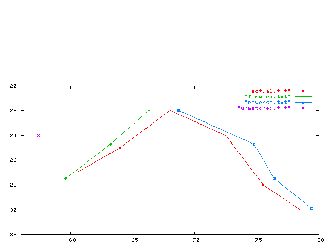
I've graphed these location measurements. Some of the "error" in the UT measurements looks to be the size of the drilled target holes.
The reason for the "same" is that the apex target hole at the least depth is being seen twice; from the Left-Hand-Side and the Right-Hand-Side of probing with the UT beam. The corresponding depths measured are identical, as would be expected. The two "x-ut's" are slightly different. This is also expected, as the location of the reflections are from opposite quadrants of a drilled hole of the finite size.
Which identifies one apparent target using UT which does not exist...
Equally, for the furthestmost drilled target hole, where it would be difficult to confuse what is being probed by the UT beam, the UT location measurement is remarkably close to the actual position...
So what to make of this???
So, I have am falsely identifying a reflector which is not there in the target block with its "upside-down tick" array of drilled target holes. Where to next...?
One of the BS4331-1 calibrations, "12. beam width", says to look out for secondary amplitude peaks which suggest a problem with the beam shape.
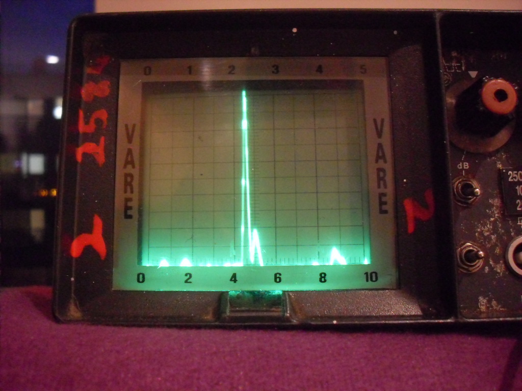
I've photographed the screen with the "45degree" probe aiming at the
"30mm depth" transverse target hole through the "Sonatest" block
beneath the centre of the radial reflector quadrant. I've shifted the
peak to the middle of the screen
(therefore timebase not meaningful; the first, "general view", picture
shows the screen for the same measurement with the timebase in
calibration of 50mm at full screen width).
Detail of the "secondary" peak:
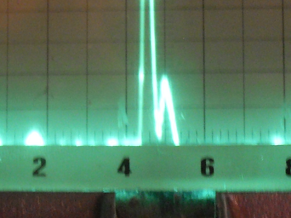
Could this be the cause of my problem accurately locating the reflectors in the test target block?
I have found angle probes harder to set-up as the angle gets steeper. The repeat echoes get smaller and difficult to identify with confidence from the noise ("grass") as you increase the input dB, trying to get them to show themselves... ???
Also finding with 60degree probe that you are getting strong
reflections from the external corners of the block which you are not
getting with the 45degree probe.???
At least you can predict when you will see them. For instance with
the 60degree probe on 19mm plate, you expect to see them at 35mm,
70mm, 105mm, etc - intervals of 35mm - from any edge the probe is
square-on to ???
With rectangular corners, the things reflect strongly over quite a
range from the peak reflection at the 35mm increments...(?) However,
you can watch the echo continuously rise to a maximum then decline,
manipulating the probe across the block, that peak being far wider
than a typical reflector echo - so you can reasonably well identify
the them...???
At least with a weld you wouldn't normally be anywhere near a corner
(???)
When having my first training, a "70degree" probe was sending out a surface wave. That was shown to me by rubbing a finger around on the block surface on the "beam" side of the probe and causing large changes in the echoes on screen.
(R Smith, 21 July 2012)