The practical engineering reasons for the interest-in and application-of these structures is developed in my skills section.
Presented here in brief are the images coming from this May 2017 "shell-element modelling of thin-plate (thick-sheet) steel structures" programme.
The component is hypothetical but representative (?) of the type of thin-plate metal "chassis" now possible for machines - replacing machine-frames made from an assembly of "sections" - angles, I-beams, tubes, channels, solid bars, etc
"Simple shell" (no stiffening ribs etc) - FEA model of such a component. These are "quarter-section", making use of the two planes-of-symmetry ("halving down the middle")
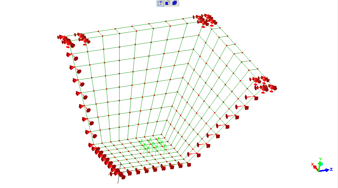
The model. Fixed at "rim" at midpoints and corners; 10kN (1 tonne-force) upwards at each "corner" of the base.
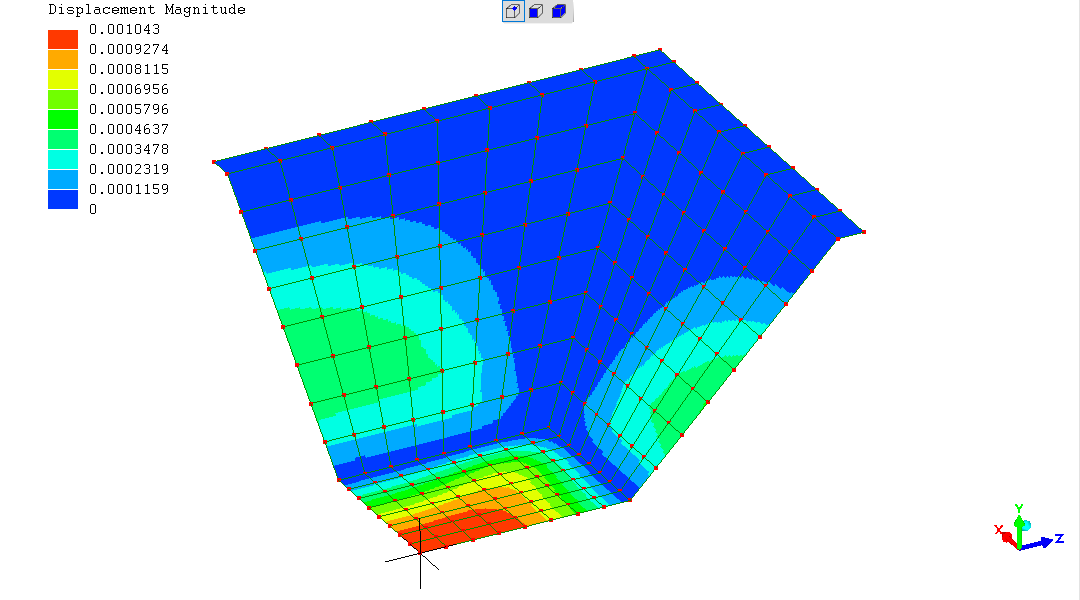
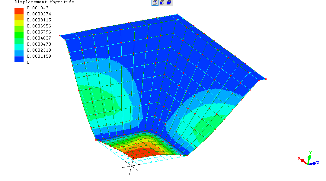
Displacement - scale is metres - "as-is" and with exaggerated deformation (x20)
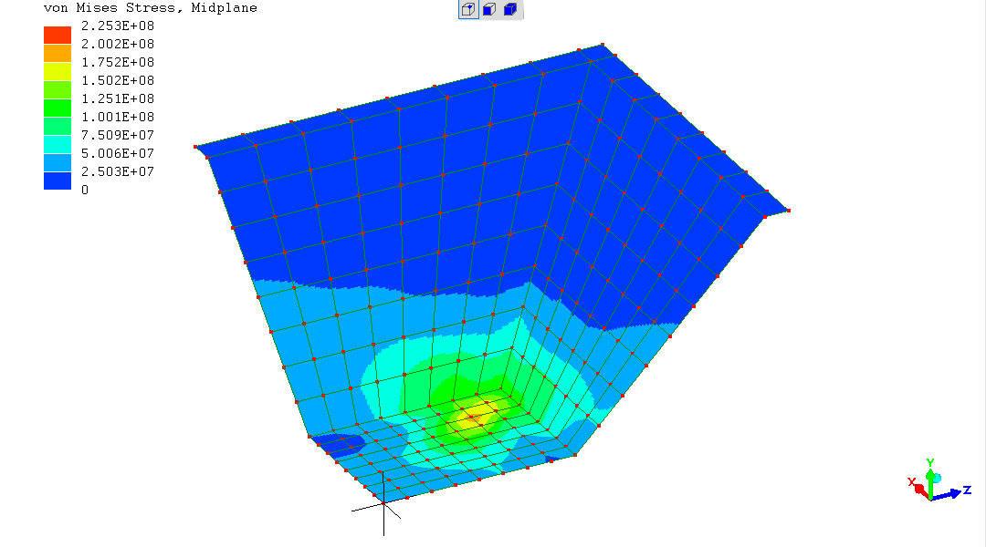
Stress - Von Mises deviatoric stress - "2.253E+08" = 225MPa, etc
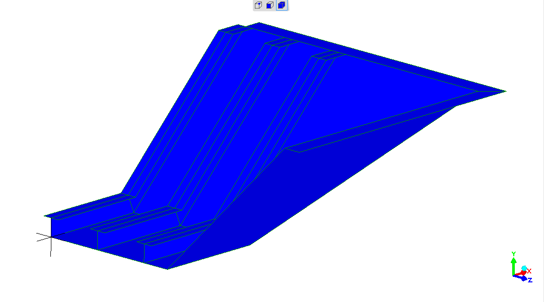
The following shows starting to add stiffener-ribs (there would be
more, and they would be in both longitudinal and transverse directions).
This is not "meshed" and cannot "solve".
Its purpose is to illustrate what the next development might be.
In seeking a lighter stiffer structure - and suggesting the attractive
mechanical-clamp mounting-points offered for electro-mechanical
components shielded within the "shell" chassis :-)
(R. Smith, 30May2017, 01Jun2017)